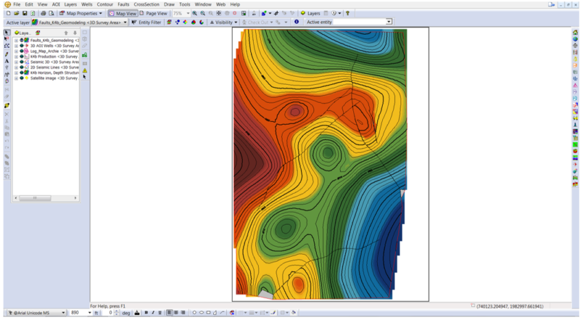
You can work with faults in GVERSE Geomodeling by selecting them from a seismic interpretation, a cross section, or by importing them into the database. Furthermore, geoscientists can create a structural model by using the Fault Network tool, assigning different levels of hierarchy to the faults in the interpretation. Turning on the Fault Offset and Fault Network tools in GVERSE Geomodeling allows you to see the vertical separation, truncations, etc. not only in the cross section, but also in 3D in Map View; where you can create a layer displaying a specific surface and the interaction of the fault(s) with that surface and export that layer into GeoAtlas.
Here’s how you can create and export a fault(s) layer in GVERSE Geomodeling:
- Open or create an interpretation in GVERSE Geomodeling.
- On the Home tab click on Geomodel Properties.
- The GeoSurface Model Properties window will open. On the Surfaces tab, check the formation tops that you want to use in the interpretation from the Formation Tops list and click Apply (the formation tops displayed are from the Active Strat Column; if you are using Data Points as a Surface Source).
- Click on the Faults tab and select the Faults under the Fault list. Click Apply (the list will change if you select Data Points or GVERSE Geophysics as a Fault Source).
- Click on the Networks tab and select a Fault name and re-organize the hierarchy level. The Fault on top of the three will control the fault under. Click Apply.
- Pick or display fault(s) in the interpretation by opening a Cross section (the more fault picks in the study, the more accurate will be the model).
- After picking or displaying the Fault(s) in the study area, go to the Home tab, select Fault Offset, Fault Networks and if you selected a Conformance surface, click on the Conformance tool. Click Update Model (You can activate the Select Fault Offset, Fault Networks and the Conformance surface on the Cross Section as well).
- The fault(s) offset and network will apply in the cross section(s), map view and 3D view.
To create a Faults Layer in a specific surface:
- On the Data Panel – 2D, select the surface that you want, right click and select Create IsoMap Layer.
- Select the Type, Sub Type and Surface, and add a Layer Name or go to the Layer tab and click on Create IsoMap Layer.
- The IsoMap build Surface: Create Layer – Display Options window will appear where you can modify the Contours, Color Fill, Grid, Data Points, and Build Parameters. Click Finish.
- Open GeoAtlas (a new map or create a map), select the layer name from the Layer Selection list and click OK. The layer will display in GeoAtlas.
To create a Fault Surface Plane Layer:
- Go to Layer tab (Create IsoMap Layer or On the Data Panel – 2D), select the surface that you want, right click and select Create IsoMap Layer. Here you can select the fault you would like to use and add a layer name.
- In the IsoMap build Surface: Create Layer – Display Options window you can modify the Contours, Color Fill, Grid, Data Points, and Build Parameters. Click Finish.
- Open GeoAtlas (a new map or create a map), select the layer name from the Layer Selection list and click OK. The layer will display in GeoAtlas.


