
An unconformity is an erosional or non-depositional surface separating strata of different ages or two rock masses, which indicates that sediment deposition was not continuous. When one surface intersects an unconformity surface, the Unconformity Trimming tool in GVERSE Geomodeling will trim or truncate the subsidiary surface, helping you create a sedimentological model for a more accurate analysis on the fly.
Here’s how you can work with unconformities in GVERSE Geomodeling:
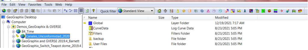
- Activate a GeoGraphix Project and open or create an interpretation in GVERSE Geomodeling.
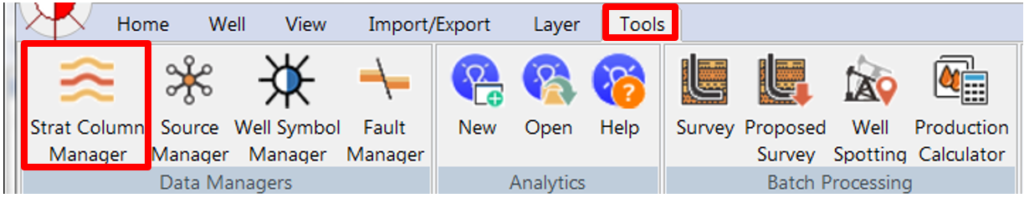
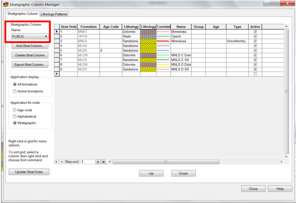
- Before using GVERSE Geomodeling, check the stratigraphic column in WellBase. Open WellBase and click Strat Column Manager in the toolbar. In the Stratigraphic Column Manager window check if you are using the correct StratColumn. The Public StratColumn is the default stratigraphic column. Users can create their own stratigraphic column.
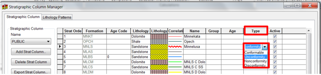
- Go to Type column, click the drop box and select if the formation top is an Unconformity, Nonconformity, or a Disconformity. After selecting, the line / symbol under correlation column will change to a wiggle line, indicating that an unconformity was selected. Click Close when finished.
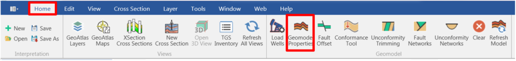
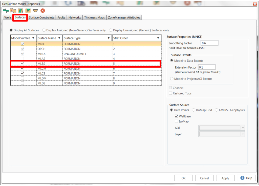
- In GVERSE Geomodeling go to Home and click on Geomodel Properties. The GeoSurface Model Properties window will open. Click Surfaces and check if the formation tops with unconformities are selected.
- Click the Surface Constraints tab and use the Surface constraints page to set up a system of constraint dependencies for surfaces. Surface constraints are defined by dragging and dropping the dependent (Constrained) surfaces under the control (Constraining) surfaces on the tree.
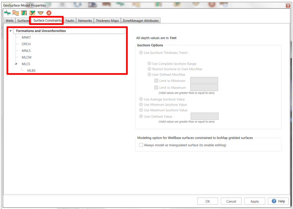
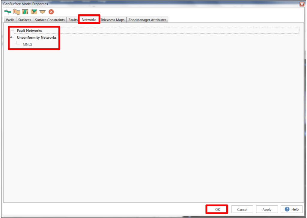
- If you have more than one unconformity; go to Networks. Fault and Unconformity networks are set up using a drag and drop operation to define parent and child relationships. The networking process requires that you define the hierarchy of each fault or Unconformity relative to each other. Click OK.
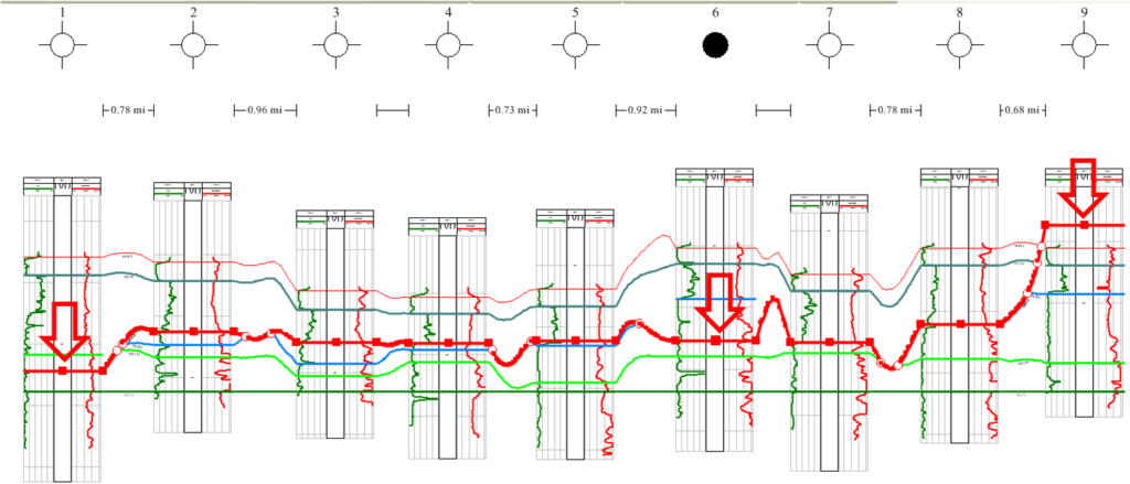
- Open or create a cross section in GVERSE Geomodeling. Recognize the formation top with unconformity in the cross section. You can always change the color and the thickness of the formation top line if necessary.
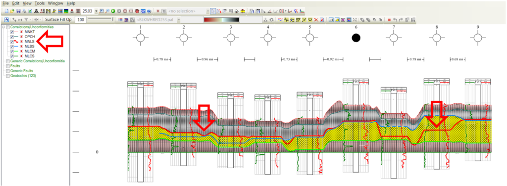
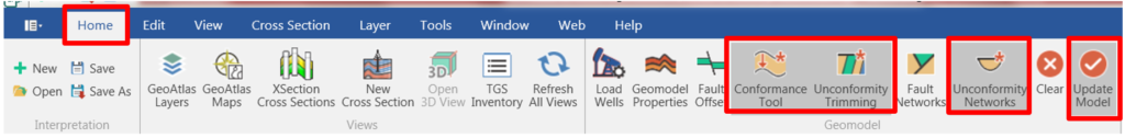
- On the cross section select the Conformance tool and the Unconformity tool. If you have more than one unconformity select the Unconformity Network. After selecting the modeling tools, click Update Model Icon (when the modeling tools are selected a red * will appear on the right corner of the tool).

- Automatically, the truncation will apply to the cross section.

- To turn off the modeling tool, uncheck all the modeling tools and click the modeling tool Update.
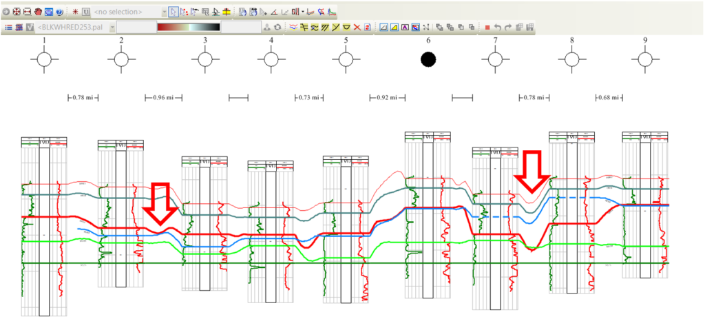
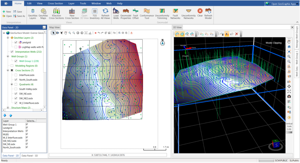
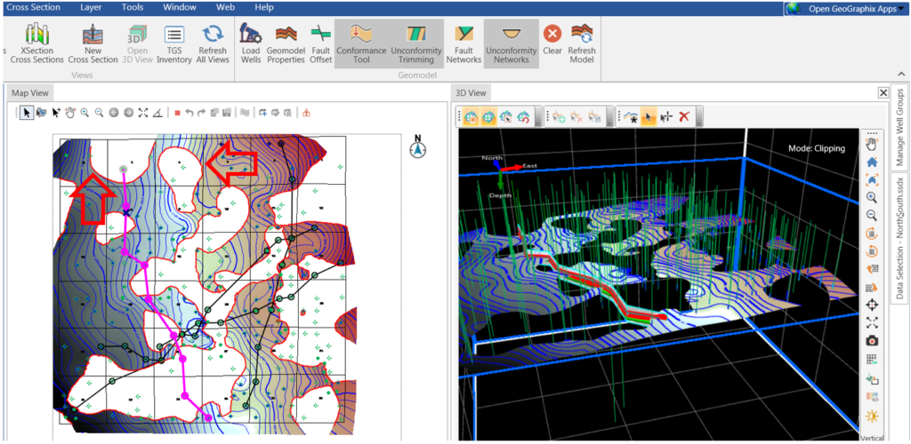
- The modeling tools can also be activated in the map view. Go to Home and select the model tools that you want to apply. Click Update Model. The truncation automatically applies not only to the cross section(s), but also in Map View and 3D View.
- If any change is applied on the cross section (moving the unconformity top), the change will apply automatically on the map view and 3D view.
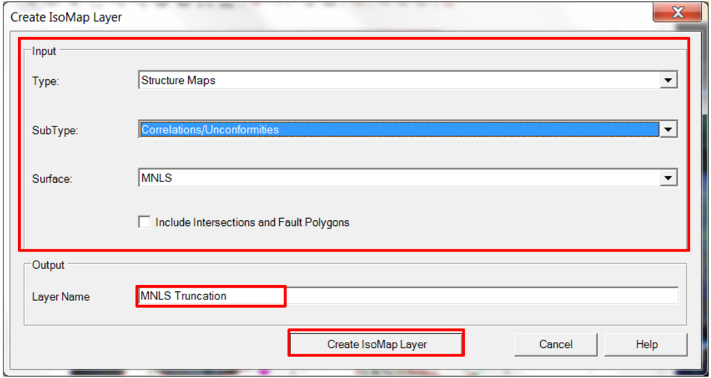
- To create an IsoMap Layer from the unconformity, on the Data Panel – 2D highlight the unconformity – formation top from the list and right click to select Create IsoMap Layer. Add a name, select the type and sub-type, and click Create IsoMap Layer.
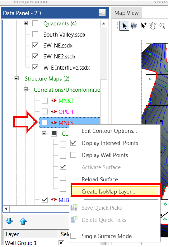
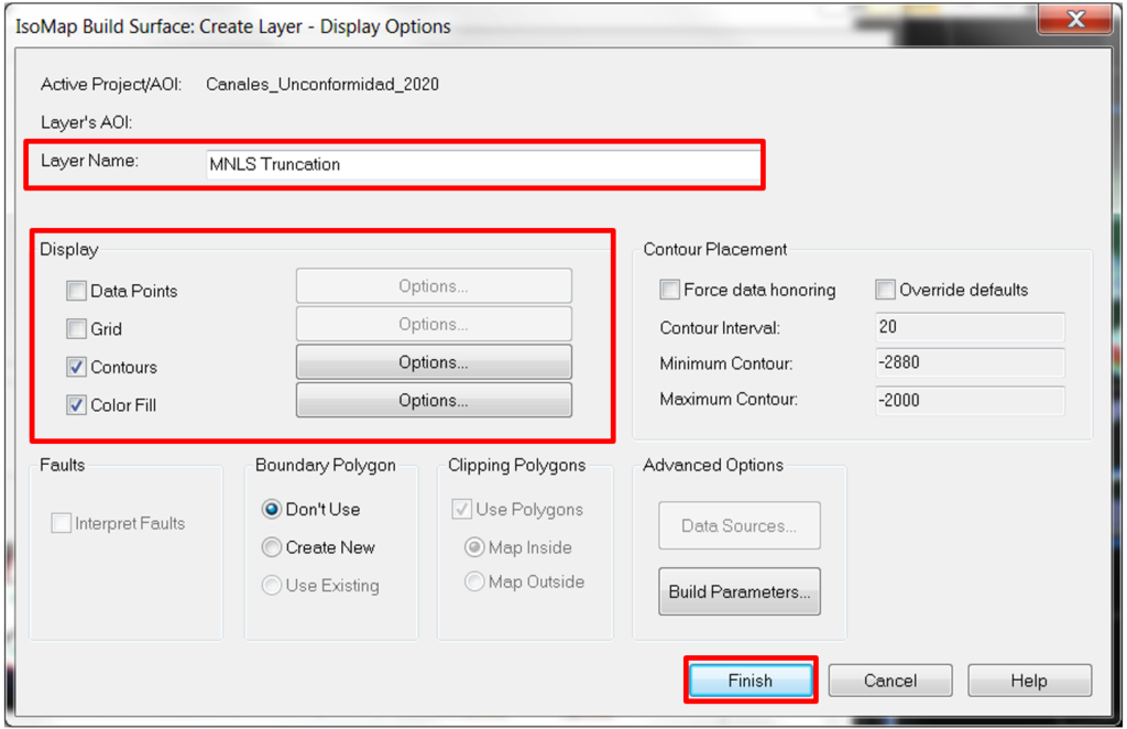
- The IsoMap Build Surface: Create Layer – Display Options window will appear. Make any changes such as Grid, Color Fill, Contours, etc. and click Finish.
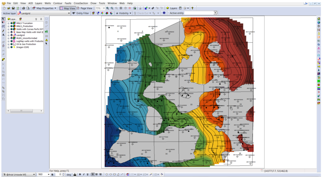
- Open GeoAtlas and add the new truncation layer to a map.